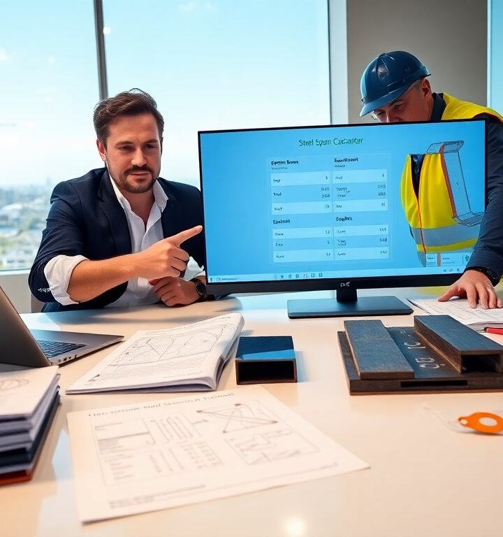

A steel i beam delivers high strength and clear load paths for many structures. This guide explains common types, standard sizes, and selection rules for engineers and builders. It uses simple rules and direct examples. It aims to help readers pick the right steel i beam for beams, columns, frames, and bridges. The following sections cover definitions, where and why engineers choose specific shapes and grades, step‑by‑step sizing guidance, and practical installation and maintenance practices that affect long‑term performance and life‑cycle cost.
Key Takeaways
- A steel I beam provides high strength and clear load paths, making it essential for beams, columns, frames, and bridges in structural applications.
- Common steel I beam types include W-shapes, S-shapes, and H-beams, selected based on load, span, and connection requirements.
- Engineers use steel I beam sizes and mechanical properties like yield strength and moment of inertia to ensure beams meet bending, shear, and deflection limits safely and economically.
- Proper installation of steel I beams involves precise lifting, alignment, welding or bolting, and immediate corrosion protection with primer and paint.
- Routine maintenance of steel I beams includes regular inspections for rust and deformation, timely repairs, and replacement of severely corroded parts to ensure longevity.
What Is A Steel I‑Beam And Where It’s Used
A steel i beam is a long, straight member with a central web and two flanges. Engineers make it from rolled or welded steel. Designers use the steel i beam for bending and shear resistance in buildings and bridges. Contractors use it as girders, floor beams, and column caps. Fabricators cut and weld the steel i beam for custom lengths. Architects specify the steel i beam to span open spaces with fewer supports. Inspectors check the steel i beam for corrosion and alignment on site. Suppliers list common steel i beam types like W-shapes, S-shapes, and H-beams. Buyers choose a steel i beam type by load, span, and connection needs.
Beyond generic descriptions, a steel i beam’s geometry—web height, flange width and thickness—determines how it resists bending and shear. W-shapes (wide‑flange) are typically used where uniform bending resistance and efficient flange geometry are required. S-shapes (American Standard) have tapered flanges and are often used in older buildings or for retrofits. H-beams and welded plate girders are chosen when large depths or customized cross sections are needed for long spans, heavy loads, or architectural constraints. Typical uses include roof and floor framing, bridge main girders and stringers, crane runways, mezzanines, and heavy industrial supports. Selection also depends on erection constraints: heavier steel i beam sections may require special rigging or temporary supports during construction, and transportation limits can dictate maximum length and weight per piece.
Standard Sizes, Grades, And Mechanical Properties You Need To Know
Manufacturers publish steel i beam sizes by depth, flange width, and mass per foot. Engineers read tables that list section modulus and moment of inertia for each steel i beam size. Common US shapes include W8x24, W10x33, and W14x48. Fabricators often stock those steel i beam sizes and larger. Steel grades matter for strength and toughness. Typical grades include ASTM A36, A572 Grade 50, and A992. Designers select A992 for building steel i beam work where weldability and yield control matter. Mechanical properties include yield strength, tensile strength, and elongation. Engineers use yield strength to size the steel i beam for bending limits. They use tensile strength to check failure modes and elongation to estimate ductility. Tables show modulus of elasticity and shear area for each steel i beam. The properties guide safe load and deflection checks.
When comparing sizes, two derived properties are especially useful: the section modulus (S) for bending checks and the moment of inertia (I) for deflection checks. For a given bending moment M, the required section modulus Sreq = M / Fy (with code factors applied) guides the minimum steel i beam section. For deflection, evaluate EI to ensure deflection limits (L/240, L/360, etc.) are met. Local buckling checks use flange and web width‑to‑thickness ratios; compact, non‑compact, and slender classifications affect allowable stresses. Practical selection also accounts for connection design—larger flanges simplify bolted connections and reduce bearing stresses, while thicker webs may require shear tabs or web stiffeners if concentrated loads or large shear forces are present. Mill certifications, heat numbers, and material traceability are standard procurement items; verify these with your fabricator, particularly for critical infrastructure or seismic applications.
Quick Sizing Checklist: How To Choose The Right I‑Beam For Your Project
Define the loads that act on the steel i beam. Engineers list live load, dead load, point loads, and wind or seismic loads. Calculate bending moment and shear for the span and support conditions. Use the steel i beam section modulus to check bending. Use moment of inertia to check deflection against limits. Pick a steel i beam size that meets strength and deflection limits with an economical weight. Check local codes and connection types for the chosen steel i beam. Verify flange and web local buckling limits for the selected steel i beam. Consider fire protection and corrosion coating when the steel i beam sits in exposed conditions. Order steel i beam material with mill certifications and delivery lead times. Coordinate cutting and cambering with the fabricator before site delivery.
To make this practical on a project: start with a quick preliminary sizing using approximate bending moment diagrams and pick a candidate steel i beam whose section modulus slightly exceeds the required Sreq. Then perform a full analysis including shear, deflection, lateral‑torsional buckling (for unbraced lengths), and connection design. Check lateral bracing spacing—longer unbraced lengths increase required section modulus for lateral‑torsional stability. For concentrated loads near supports, review bearing capacity at flange contacts and consider seat angles or stiffened bearing plates. Always confirm that erection tolerances, camber requirements, and transport limits (length, weight per piece) fit the project logistics. Finally, include a contingency for field modifications: mark and ship pieces with sufficient access and bolt patterns to accommodate slight on‑site adjustments.
Key Installation, Handling, And Maintenance Best Practices
Plan lifting points and rigging for each steel i beam before lift. Crews tag and match-mark each steel i beam to shop drawings. Installers set the steel i beam on temporary supports and check level and plumb. Welders and bolters attach the steel i beam per the connection design. Inspect welds and bolts after each critical splice on the steel i beam. Apply primer and paint to the steel i beam soon after installation to reduce corrosion. Schedule periodic inspections for the steel i beam to check for rust, deformation, or loose connections. Repair damaged areas by grinding back to clean steel and recoat the steel i beam. Replace severely corroded steel i beam components rather than patching them. Store spare steel i beam pieces under cover and off the ground to prevent moisture damage.
Additional practical tips: use soft slings or wide lifting straps to avoid flange damage during lifts, and protect painted surfaces with sacrificial covers during construction. When welding on site, control heat input and follow preheat/post‑weld practices recommended for the chosen steel grade to avoid brittle zones. For inspection, maintain a simple log listing date, location on the steel i beam (web, top flange, bottom flange, connections), findings, and corrective actions; include photographs for trend tracking. For structures in corrosive environments, plan for sacrificial coatings, cathodic protection, or periodic full‑section replacement intervals as part of asset management. Finally, coordinate with your fabricator to include shop‑installed stiffeners, copes, and predrilled bolt holes to reduce field welding and speed erection while ensuring the steel i beam performs as designed.